Compound Parabolic Concentrator (CPC)
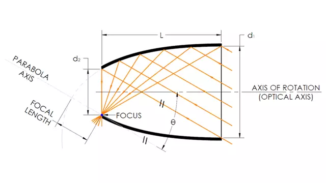
Electroformed CPCs increase the efficiency of wave energy collection and concentration.
- Collimates a Light Source or Concentrates Light from Distant Sources
- Applications Include: Solar Energy Collection, Fiber Optics, Biomedical, Defense Research
- Surface Enhancements: Electro-deposited Platings, Optical Coatings
Optiforms Off-the-Shelf Compound Parabolic Concentrators
| Part Number | Input (mm) | Input (in) | Output (mm) | Output (in) | I/O Ratio | Acceptance angle * | Acceptance angle total ** | Length (mm) | Length (in) |
|---|---|---|---|---|---|---|---|---|---|
| CPC1 | 83.21 | 3.276 | 25.4 | 1.000 | 3.3 | 17.8 | 35.6 | 169.39 | 6.669 |
| CPC2 | 8.38 | 0.330 | 0.84 | 0.033 | 10.0 | 5.3 | 10.6 | 43.99 | 1.732 |
| CPC3 | 8.38 | 0.330 | 1.93 | 0.076 | 4.3 | 5.3 | 10.6 | 43.15 | 1.699 |
| CPC4 | 57.53 | 2.265 | 10.00 | 0.394 | 5.7 | 10.0 | 20.0 | 180.00 | 7.087 |
| CPC5 | 86.4 | 3.401 | 15.00 | 0.591 | 5.8 | 10.0 | 20.0 | 287.48 | 11.318 |
| CPC6 | 148.54 | 5.848 | 50.80 | 2.000 | 2.9 | 20.00 | 40.0 | 273.86 | 10.782 |
| CPC7 | 4.6 | 0.181 | 1.52 | 0.0600 | 3.0 | 12.0 | 24.0 | 5.00 | 0.197 |
| CPC8 | 46.10 | 1.815 | 6.35 | 0.250 | 7.3 | 16.0 | 32.0 | 104.39 | 4.110 |
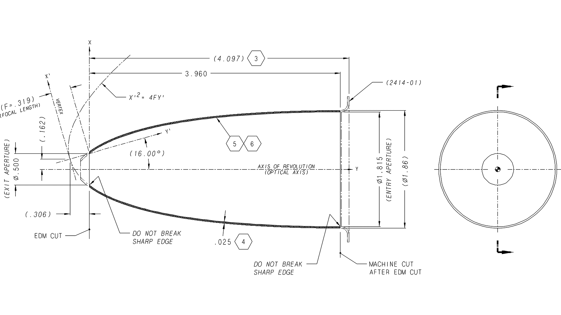
| CPC9 | 46.10 | 1.815 | 12.70 | 0.500 | 3.6 | 16.0 | 32.0 | 100.58 | 3.960 |
| CPC10 | 10.00 | 0.394 | 3.94 | 0.155 | 2.5 | 16.3 | 32.5 | 22.58 | 0.889 |
Need a Custom Compound Parabolic Concentrator?
Custom Dimensions Available
CPCs are commonly used in solar energy collection, fiber optics, biomedical and defense research, or other applications that require condensing of divergent light sources.
These non-imaging components concentrate light rays that are not necessarily parallel nor aligned with the axis of the concentrator.
Considerations for CPC Manufacturing
Optiforms fabricates hollow, thin wall CPC’s using electroforming technology (See Figure 1). The substrate is Nickel with a specular internal surface. The advantage to this is that the light energy does not need to pass through the surfaces of glass upon entrance and exit.
In the electroforming process, the inside surface is replicated from the highly polished master tool, which eliminates any further polishing of the inside surface after the part is separated from the master tool.
Although the inside surface has a highly specular finish, it is made of nickel which does not reflect well in the Electromagnetic Spectrum. To get the desired % Reflectance requires additional processes to enhance the inside optical surface. Optiforms can apply physical vapor despoited (PVD) coatings or electro-deposited platings to increase the % Reflectance for the desired wavelengths of interest.
See below for surface finish options and limitations:
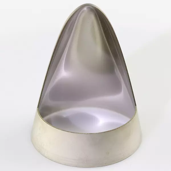
Enhanced Surface Finishes for Compound Parabolic Concentrators
Electro-deposited Platings
Also known as electroplating, electrodeposition is a metal coating process where a component is overlayed with another type of metal through an electrochemical reaction to enhance its surface properties. Optiforms’ standard electro-deposited platings are rhodium and gold.
Physical Vapor Deposited Coatings
If your application requires reflectance in the UV spectrum or you require higher reflectance in the visible spectrum than what rhodium can provide, consider our physical vapor deposited coatings (also referred to as vacuum coatings). See all Physical Vapor Deposited Coatings
It should be noted that because vacuum coatings are a line-of-sight process, most electroformed CPCs cannot be vacuum coated due to their high aspect ratio (proportion of depth versus length), which prevents acceptable uniformity of the optical coating. We offer several options to address this issue:
Option A - Center Cut
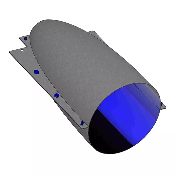
After the electroforming process, we use a wire electrical discharge machine (EDM) to cut the CPC down the middle, along the optical axis. There is a .013” (.30mm) kerf loss when we wire EDM cut CPCs in half, which is based on the wire thickness used in the EDM process. What this means is the CPC halves are no longer true halves – each half is now missing .0065” (.15mm) of material along the optical axis. When we go to put the CPC halves back together using machined aluminum alignment rings and epoxy, it is no longer a perfect concentric CPC since it is now missing the material along the optical axis from the EDM cut. Some of our customers opt for this method and report that it does not have a significant impact on how the optic works for their specific applications. (See Figure 2)
Option B - Off-set Cut
Another manufacturing option is to offset the wire EDM cut, so all the kerf loss is on one sideof the optical axis cut. We end up with one true full CPC half along the optical axis, and scrap the other half, which is not full due to the kerf loss. Next, we wire EDM cut another CPC and do the same thing. We then end up with two true full halves that can be coated and put together using machined aluminum rings and epoxy, to form a full CPC. For this wire EDM process we need to make two electroformed CPCs, wire EDM cut, and we net two true halves, and two scrap halves, so it takes two electroformed CPCs to net one finished part. (See Figure 3)
Option C - Electroform halves
A third manufacturing option is electroforming the CPC in halves to begin with. This eliminates the kerf loss because a wire EDM is not used in this method. (See Figure 4)
We currently only offer two of our CPCs in this type of configuration. See CPC5 & CPC6 in our standard product table above for details.
If you require a custom CPC master tool with a PVD coated internal optical surface, this is by far the best approach.
CPC Worksheet
There are four primary variables which define any CPC: Acceptance Angle (𝜽), Input Diameter (𝒅𝟏), Output Diameter (𝒅𝟐), and Length (𝑳). A mathematically proven relationship between these variables provides a method for designers and manufacturers to easily configure a CPC for any applicable purpose within the physical constraints governing light concentration (Conservation of Étendue).
We have created this helpful worksheet to configure a Compound Parabolic Concentrator to help designers quickly define their variables.
Learn More About Custom CPC Design
Electroforming Process
The electroforming manufacturing method generates an exact copy via replication in metal (typically nickel) of a master mandrel by a process called electrodeposition. Specific benefits of electroforming are low unit costs, exact atomic scale, repeatability and excellent process control for quality. Often times the design engineer will find electroforming is preferred for many applications requiring a complex true geometric shape form factor, thin walls, and high repeatability.

